Cyclic Coordinate Descent in 2D

CCD solves the IK problem through optimization. Looping through the joints from end to root, we optimize each joint to get the end effector (tip of the final joint) as close to our target as possible. This loop is then repeated until we find a solution or we reach an iteration limit. You can download the RJ_Demo_IK application and source code to see an interactive implementation.
You might also be interested in the following articles on different IK solvers:
Optimizing a joint
In math, optimization in the process of finding a value that will minimize or maximize a function. In our case, we want to minimize the distance between the end effector and the target (i.e. minimize \(|\mathbf{e}-\mathbf{t}|\) for end effector, \(\mathbf e\), and target, \(\mathbf t\)). Depending on how our joints behave, different equations will be used to find the optimal solution. For example, one joint might allow for translation while another joint might allow rotation.
For common joint behavior, we can develop an analytic solution to find the optimal value. I am going to walk through solving the optimization problem for rotational joints (the most common joint behavior in an animated character).
As a rotational joint, we can rotate the end effector in a circle about our position (see figure 1). The closest position to the target on our rotational circle is the intersection of the circle and the line segment between the current joint and the target.

figure 1
To move the end effector to its optimal position, we need to rotate the joint by the unknown value \(\alpha\). We know the current joint position, \(\mathbf j\), the current end effector position, \(\mathbf e\), and the target position, \(\mathbf t\). To find \(\alpha\), we need to find the angle that will rotate \(\mathbf e\) around \(\mathbf j\) onto the line \((\mathbf{t} - \mathbf{j})\). This makes \(\alpha\) the signed angle between the vectors \((\mathbf{e} - \mathbf{j})\) and \((\mathbf{t} - \mathbf{j})\) that rotates \((\mathbf{e} - \mathbf{j})\) to \((\mathbf{t} - \mathbf{j})\).
Solving for cosine
The dot product can be geometrically interpreted as \(\mathbf{a} \cdot \mathbf{b} = |\mathbf{a}| |\mathbf{b}| \cos \theta\) where \(|\mathbf{a}|\) is the length of vector \(\mathbf{a}\), \(|\mathbf{b}|\) is the length of vector \(\mathbf{b}\), and \(\theta\) is the smaller angle between vector \(\mathbf{a}\) and vector \(\mathbf{b}\). Using this formula, we can solve for the cosine of \(\alpha\).
\((\mathbf{e} - \mathbf{j}) \cdot (\mathbf{t} - \mathbf{j}) = |\mathbf{e} - \mathbf{j}| |\mathbf{t} - \mathbf{j}| \cos \alpha\)
\(\cos \alpha = \frac{ (\mathbf{e} - \mathbf{j}) \cdot (\mathbf{t} - \mathbf{j})}{|\mathbf{e} - \mathbf{j}| |\mathbf{t} - \mathbf{j}| }\)
Solving for sine
The cosine alone will help us find the magnitude of \(\alpha\), but it won't supply us with the direction of rotation. To find the direction, we need to compute \(\sin \alpha\). The three-dimensional cross product can be geometrically interpreted as \(\mathbf{a} \times \mathbf{b} = |\mathbf{a}| |\mathbf{b}| \sin \theta \mathbf{n}\) where \(\mathbf n\) is the unit vector perpendicular to vector \(\mathbf a\) and vector \(\mathbf b\) pointing in the direction defined by the right-hand rule, and \(\theta\) is the unsigned smaller angle between vector \(\mathbf{a}\) and vector \(\mathbf{b}\). While \(\theta\) is an unsigned angle, we will be able to get the direction of our rotation based on the direction of \(\mathbf n\)
First, let's expand the cross product of two three-dimensional vectors.
\(\begin{bmatrix}a_x\\a_y\\a_z\end{bmatrix} \times \begin{bmatrix}b_x\\b_y\\b_z\end{bmatrix} = \begin{bmatrix}a_y b_z - a_z b_y\\a_z b_x - b_z a_x\\a_x b_y - a_y b_x\end{bmatrix}\)
If we interpret our two-dimensional vectors as three-dimensional vectors on the xy-plane, the cross product will result in a three dimensional vector pointing along the z-axis.
\(\begin{bmatrix}a_x\\a_y\\0\end{bmatrix} \times \begin{bmatrix}b_x\\b_y\\0\end{bmatrix} = \begin{bmatrix}0\\0\\a_x b_y - a_y b_x\end{bmatrix}\)
Looking back at our geometric interpretation of the cross product, \(\mathbf{a} \times \mathbf{b} = |\mathbf{a}| |\mathbf{b}| \sin \theta \mathbf{n}\), the unit vector \(\mathbf n\) must be either the negative or positive z-axis. Combining our expanded cross-product with the geometric interpretation, we get the following relation where \(n_z\) is either -1 or 1.
\(\begin{bmatrix}0\\0\\a_x b_y - a_y b_x\end{bmatrix} = |\mathbf{a}| |\mathbf{b}| \sin \theta \begin{bmatrix}0\\0\\n_z\end{bmatrix}\)
We can now focus on the z-components of our equation (x and y were zeros).
\(a_x b_y - a_y b_x = |\mathbf{a}| |\mathbf{b}| \sin \theta n_z\)
The value of \(n_z\) determines if we are rotating in clockwise or counter-clockwise direction. In a right-handed coordinate system where the x-axis points right and the y-axis points up, the z-axis will point forward. According to the right-hand rule, \(\mathbf n\) will be the negative z-axis when we are rotating clockwise and \(\mathbf n\) will be the positive z-axis when we are rotating counter-clockwise. This implies that \(n_z\) is -1 for clockwise rotations and 1 for counter-clockwise rotations.
Because \(\theta\) is the smaller angle between two vectors, it is in the positive range \([0,\pi]\). Positive angles result in counter-clockwise rotations. Negative angles result in clockwise rotations. Given that \(-\sin{x} = \sin (-x)\), when \(n_z\) is -1, \(n_z \sin \theta = -\sin \theta = \sin (-\theta)\). Previously, we concluded that a negative value of \(n_z\) implies a clockwise rotation which in turn implies a negative rotation angle. This will let us define a new signed angle, \(\phi\) that is the directional rotation from vector \(\mathbf a\) to vector \(\mathbf b\).
\(a_x b_y - a_y b_x = |\mathbf{a}| |\mathbf{b}| \sin \theta n_z = |\mathbf{a}| |\mathbf{b}| \sin \phi\)
\(a_x b_y - a_y b_x =|\mathbf{a}| |\mathbf{b}| \sin \phi\)
Using this equation, we can substitute for \(a\), \(b\), and \(\phi\) to solve for the sine of \(\alpha\).
\((e_x - j_x)(t_y - j_y)-(e_y - j_y) (t_x - j_x) = |\mathbf{e} - \mathbf{j}| |\mathbf{t} - \mathbf{j}| \sin \alpha\)
\(sin \alpha = \frac {(e_x - j_x)(t_y - j_y)-(e_y - j_y)(t_x - j_x)} {|\mathbf{e} - \mathbf{j}| |\mathbf{t} - \mathbf{j}|}\)
We now have equations for solving the sine and cosine of a signed angle between two vectors. This will let us perform the appropriate rotation for our joint.
Visualizing CCD
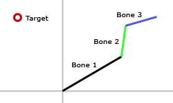
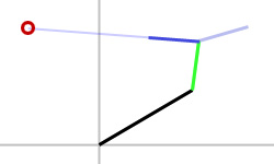
To help visualize the algorithm, let's run through a single iteration of CCD on a small kinematic chain of rotational joints.
| Initial kinematic chain orientation. |
 |
| Rotate bone 3 to place end effector as close to target as possible. |
 |
| Rotate bone 2 to place end effector as close to target as possible. |
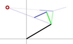 |
| Rotate bone 1 to place end effector as close to target as possible. |
 figure 2d |
After our first loop through the bone chain, we have moved the end effector much closer to the target position. By repeating this process, we will continue to get closer and closer. Once we have reached a tolerable distance from the target position or once we have performed too many iterations (for performance reasons), we can stop looping. If we didn't manage to find a solution on one frame, we can supply the updated joints as the starting CCD values on the next frame (essentially distributing a larger number of iterations over multiple frames).
Local Minima
Unfortunately, there are some kinks with CCD. From certain initial poses, the algorithm will fail to find the proper solution to a problem. I don't know of any CCD literature that discusses (or really even mentions) this subject, but I will show an example problem. Fortunately, this doesn't often come up in practice and depending on the requirements of your IK simulation and the mobility of your kinematic chain, you may be able to ignore it.
Given a two bone chain where both bones start with no rotation, we can place the target in a position that will lock up CCD at an invalid result. Our initial setup can be seen in figure 3a.
| Initial orientation. |
 |
If CCD was able to give us a valid solution, bone1 would bend away from the target allowing bone2 to bend towards the target. One possible valid solution is shown in figure 3b.
| Desired solution orientation. |
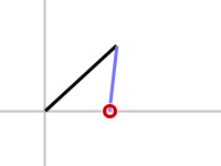 figure 3b |
When actually performing the CCD algorithm, we will get stuck at a local minimum (see figure 3c). The first step of CCD will rotate bone2 to point towards the target. This will result in a rotation of 180 degrees and will get the end effector as close to the target as possible with regards to the mobility of bone2. It is now bone1's turn to place the end effector as close to the target as possible. It turns out that bone1 is already in the optimal position and therefore does nothing. We are now in a situation where both bones are in optimal positions and they will no longer move as we continue to iterate the algorithm.
| Resulting orientation. |
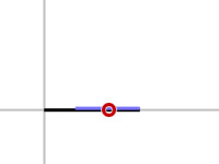 |
It should be noted that if the joints had rotational constraints (could not spin 180 degrees), we would have avoided this singularity, but adding rotational constraints can lead to a whole new set of local minima.
CCD considers one joint at a time with no real care about how the rest of the joints behave. The only part of the algorithm that even recognizes the joint hierarchy is the requirement that we loop backwards from the end joint to the root joint. It should also be noted that the individual steps of the algorithm aren't aware that they are part of a larger iteration towards a solution. This results in a fairly myopic view of the larger IK problem when optimizing a single joint.
We are computing the joint orientation that will instantly get the end effector to the optimal position for the current joint. If we were a bit less selfish, we could consider the limitations of the other joints when defining what our optimal orientation actually is. This steps a bit away from the pure CCD algorithm which tries to minimize the error from the target position one joint at a time. Is there some new equation we would be minimizing by taking the rest of the hierarchy into account? In the past, I've tried adding some conditions to detect undesired solutions, but am yet to build something robust enough to handle all problem cases while maintaining efficiency.
Writing the code
Now that we've covered the basic building blocks of CCD, we can write an implementation that solves a kinematic chain consisting of any number of rotational joints. The function will perform a single iteration of CCD, by updating a supplied chain of joints. The user can then iteratively resupply the updated values until a valid solution is found, an iteration limit is reached, or the end effector stops updating due to the target being out of range. Check out the RJ_Demo_IK application for a sample implementation of the code.
These code samples are released under the following license.
/******************************************************************************
  Copyright (c) 2008-2009 Ryan Juckett
  http://www.ryanjuckett.com/

  This software is provided 'as-is', without any express or implied
  warranty. In no event will the authors be held liable for any damages
  arising from the use of this software.

  Permission is granted to anyone to use this software for any purpose,
  including commercial applications, and to alter it and redistribute it
  freely, subject to the following restrictions:

  1. The origin of this software must not be misrepresented; you must not
     claim that you wrote the original software. If you use this software
     in a product, an acknowledgment in the product documentation would be
     appreciated but is not required.

  2. Altered source versions must be plainly marked as such, and must not be
     misrepresented as being the original software.

  3. This notice may not be removed or altered from any source
     distribution.
******************************************************************************/
When working with two dimensional rotations, it is often useful to wrap angles outside of the \([-\pi,\pi]\) range back into the \([-\pi,\pi]\) range. The CCD function makes use of this helper function to do so.
///***************************************************************************************
/// SimplifyAngle
/// This function will convert an angle to the equivalent rotation in the range [-pi,pi]
///***************************************************************************************
private static double SimplifyAngle(double angle)
{
    angle = angle % (2.0 * Math.PI);
    if( angle < -Math.PI )
        angle += (2.0 * Math.PI);
    else if( angle > Math.PI )
        angle -= (2.0 * Math.PI);
    return angle;
}
Internal to the CCD function we store cosine and sine values for each bone as we convert the bones into a world space representation. We can then reuse these angles throughout the function. This structure is used to assist in that process.
///***************************************************************************************
/// Bone_2D_CCD_World
/// This class is used internally by the CalcIK_2D_CCD function to represent a bone in
/// world space.
///***************************************************************************************
private class Bone_2D_CCD_World
{
    public double x;        // x position in world space
    public double y;        // y position in world space
    public double angle;    // angle in world space
    public double cosAngle; // sine of angle
    public double sinAngle; // cosine of angle
};
The user can early out of their iteration loop if the CCD algorithm detected a success state (end effector reached the target) of failure state (end effector was not moved).
///***************************************************************************************
/// CCDResult
/// This enum represents the resulting state of a CCD iteration.
///***************************************************************************************
public enum CCDResult
{
    Success,    // the target was reached
    Processing, // still trying to reach the target
    Failure,    // failed to reach the target
}
To reduce the number of parameters, the following class is used to represent an input bone.
///***************************************************************************************
/// Bone_2D_CCD
/// This class is used to supply the CalcIK_2D_CCD function with a bone's representation
/// relative to its parent in the kinematic chain.
///***************************************************************************************
public class Bone_2D_CCD
{
    public double x;     // x position in parent space
    public double y;     // y position in parent space
    public double angle; // angle in parent space
};
The following function performs a single iteration of CCD including the singularity test.
///***************************************************************************************
/// CalcIK_2D_CCD
/// Given a bone chain located at the origin, this function will perform a single cyclic
/// coordinate descent (CCD) iteration. This finds a solution of bone angles that places
/// the final bone in the given chain at a target position. The supplied bone angles are
/// used to prime the CCD iteration. If a valid solution does not exist, the angles will
/// move as close to the target as possible. The user should resupply the updated angles
/// until a valid solution is found (or until an iteration limit is met).
///
/// returns: CCDResult.Success when a valid solution was found.
///          CCDResult.Processing when still searching for a valid solution.
///          CCDResult.Failure when it can get no closer to the target.
///***************************************************************************************
public static CCDResult CalcIK_2D_CCD
(
    ref List<Bone_2D_CCD> bones, // Bone values to update
    double targetX,              // Target x position for the end effector
    double targetY,              // Target y position for the end effector
    double arrivalDist           // Must get within this range of the target
)
{
     // Set an epsilon value to prevent division by small numbers.
    const double epsilon = 0.0001;

    // Set max arc length a bone can move the end effector an be considered no motion
    // so that we can detect a failure state.
    const double trivialArcLength = 0.00001;


    int numBones = bones.Count;
    Debug.Assert(numBones > 0);

    double arrivalDistSqr = arrivalDist*arrivalDist;

    //===
    // Generate the world space bone data.
    List<Bone_2D_CCD_World> worldBones = new List<Bone_2D_CCD_World>();

    // Start with the root bone.
    Bone_2D_CCD_World rootWorldBone = new Bone_2D_CCD_World();
    rootWorldBone.x = bones[0].x;
    rootWorldBone.y = bones[0].y;
    rootWorldBone.angle = bones[0].angle;
    rootWorldBone.cosAngle = Math.Cos( rootWorldBone.angle );
    rootWorldBone.sinAngle = Math.Sin( rootWorldBone.angle );
    worldBones.Add( rootWorldBone );

    // Convert child bones to world space.
    for( int boneIdx = 1; boneIdx < numBones; ++boneIdx )
    {
        Bone_2D_CCD_World prevWorldBone    = worldBones[boneIdx-1];
        Bone_2D_CCD curLocalBone = bones[boneIdx];

        Bone_2D_CCD_World newWorldBone = new Bone_2D_CCD_World();
        newWorldBone.x = prevWorldBone.x + prevWorldBone.cosAngle*curLocalBone.x
                                         - prevWorldBone.sinAngle*curLocalBone.y;
        newWorldBone.y = prevWorldBone.y + prevWorldBone.sinAngle*curLocalBone.x
                                         + prevWorldBone.cosAngle*curLocalBone.y;
        newWorldBone.angle = prevWorldBone.angle + curLocalBone.angle;
        newWorldBone.cosAngle = Math.Cos( newWorldBone.angle );
        newWorldBone.sinAngle = Math.Sin( newWorldBone.angle );
        worldBones.Add(newWorldBone);
    }

    //===
    // Track the end effector position (the final bone)
    double endX = worldBones[numBones-1].x;
    double endY = worldBones[numBones-1].y;

    //===
    // Perform CCD on the bones by optimizing each bone in a loop
    // from the final bone to the root bone
    bool modifiedBones = false;
    for( int boneIdx = numBones-2; boneIdx >= 0; --boneIdx )
    {
        // Get the vector from the current bone to the end effector position.
        double curToEndX = endX - worldBones[boneIdx].x;
        double curToEndY = endY - worldBones[boneIdx].y;
        double curToEndMag = Math.Sqrt( curToEndX*curToEndX + curToEndY*curToEndY );

        // Get the vector from the current bone to the target position.
        double curToTargetX = targetX - worldBones[boneIdx].x;
        double curToTargetY = targetY - worldBones[boneIdx].y;
        double curToTargetMag = Math.Sqrt(   curToTargetX*curToTargetX
                                           + curToTargetY*curToTargetY );

        // Get rotation to place the end effector on the line from the current
        // joint position to the target postion.
        double cosRotAng;
        double sinRotAng;
        double endTargetMag = (curToEndMag*curToTargetMag);
        if( endTargetMag <= epsilon )
        {
            cosRotAng = 1;
            sinRotAng = 0;
        }
        else
        {
            cosRotAng = (curToEndX*curToTargetX + curToEndY*curToTargetY) / endTargetMag;
            sinRotAng = (curToEndX*curToTargetY - curToEndY*curToTargetX) / endTargetMag;
        }

        // Clamp the cosine into range when computing the angle (might be out of range
        // due to floating point error).
        double rotAng = Math.Acos( Math.Max(-1, Math.Min(1,cosRotAng) ) );
        if( sinRotAng < 0.0 )
            rotAng = -rotAng;

        // Rotate the end effector position.
        endX = worldBones[boneIdx].x + cosRotAng*curToEndX - sinRotAng*curToEndY;
        endY = worldBones[boneIdx].y + sinRotAng*curToEndX + cosRotAng*curToEndY;

        // Rotate the current bone in local space (this value is output to the user)
        bones[boneIdx].angle = SimplifyAngle( bones[boneIdx].angle + rotAng );

        // Check for termination
        double endToTargetX = (targetX-endX);
        double endToTargetY = (targetY-endY);
        if( endToTargetX*endToTargetX + endToTargetY*endToTargetY <= arrivalDistSqr )
        {
            // We found a valid solution.
            return CCDResult.Success;
        }

        // Track if the arc length that we moved the end effector was
        // a nontrivial distance.
        if( !modifiedBones && Math.Abs(rotAng)*curToEndMag > trivialArcLength )
        {
            modifiedBones = true;
        }
    }

    // We failed to find a valid solution during this iteration.
    if( modifiedBones )
        return CCDResult.Processing;
    else
        return CCDResult.Failure;
}
Comments